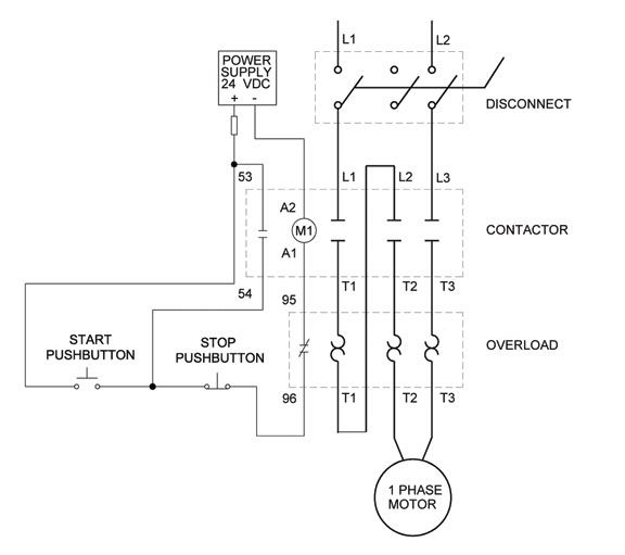
When it comes to wiring a fan motor, whether it's a single phase or three phase motor, it's essential to understand the wiring diagram to ensure proper installation and operation. In this blog, we will discuss the single phase fan motor wiring diagram and the three phase fan motor wiring diagram.

Single Phase Fan Motor Wiring Diagram
Single phase fan motors are often found in household appliances, such as ceiling fans, exhaust fans, and air conditioning units. They can also be used in industrial applications for small machinery and equipment.
The single phase fan motor wiring diagram includes the following components:
1. Power supply: The power supply is connected to the L1 and L2 terminals of the motor.
2. Starting capacitor: The starting capacitor is designed to provide the necessary voltage boost to the motor during startup. It is connected between the L1 terminal and the start winding of the motor.
3. Running capacitor: The running capacitor is used to maintain the motor's operating voltage during operation. It is connected between the L1 and the run winding of the motor.
4. Centrifugal switch: The centrifugal switch is used to disconnect the starting capacitor from the circuit once the motor reaches a certain speed. It is connected between the start winding and the neutral wire.
5. Thermal overload protector: The thermal overload protector is designed to protect the motor from overheating. It is connected in series with the L1 terminal.
Three Phase Fan Motor Wiring Diagram
Three-phase fan motors are commonly used in industrial applications, such as pumps, compressors, and blowers. They require a three-phase power supply to operate.
The three-phase fan motor wiring diagram includes the following components:
1. Power supply: The power supply is connected to the L1, L2, and L3 terminals of the motor.
2. Contactors: The contactors are used to switch the motor's power supply on and off. They are connected to the L1, L2, and L3 terminals.
3. Thermal overload protector: The thermal overload protector is designed to protect the motor from overheating. It is connected in series with the L1 terminal.
4. Run capacitor: The run capacitor is used to provide a phase shift to the motor's windings, which helps improve its efficiency. It is connected between the L1-L2, L2-L3, and L3-L1 terminals.
Conclusion
Whether you're dealing with a single phase or three phase fan motor, understanding the wiring diagram is crucial. It ensures proper installation and operation and avoids potential hazards. We hope this blog has helped you gain a better understanding of the Single Phase Fan Motor Wiring Diagram and Three Phase Fan Motor Wiring Diagram.